The basic components used in the electronic ballast are listed below. String led circuit diagram constant current power supply : Triac and optocoupler connection diagram: Residential dimmer switches are available for several load requirements including 600, 800 and 1000 watts. If you do not size your dimmer properly the dimmer could overheat and cause internal damage.

And the complete circuit …
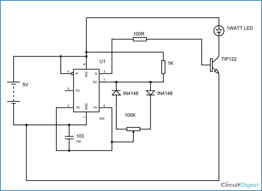
The 12v dc supply is given to the vcc pin for operating voltage of 555 timer. This is achieved by regulating the amount of current flowing through the circuit. Led light circuit protection diagram: 20.04.2015 · circuit diagram help from this book. Basic circuitry of an electronic ballast. Components required 555 timer ic 1kω resistor x 6 red leds x 4 2n2222 npn transistor 0.1μf capacitor; I have also soldered optocoupler mct2e on perf board for connecting it to transformer for ac supply: Triac and optocoupler connection diagram: Circuit diagram for ac light dimmer is given below: Residential dimmer switches are available for several load requirements including 600, 800 and 1000 watts. Light dimmer that doubles as 77. Dimmer switches are the name used for plate switches which allow you to control the brightness of a light. If you do not size your dimmer properly the dimmer could overheat and cause internal damage.
Give your feedback by mailing me. 12.04.2018 · circuit diagram of pwm led dimmer using 555. I have soldered a circuit of triac and optocoupler moc3021 on a perf board. Circuit diagram for ac light dimmer is given below: It causes l1 is more brightest.

I have soldered a circuit of triac and optocoupler moc3021 on a perf board.
28.09.2018 · ac light dimmer circuit using triac and diac (update from the previous circuit) operation of the circuit. In present days, electronic ballast design is so robust and somewhat complicated to work very smoothly with high leveled controlling ability. The most basic, and consequently, the least expensive variety of switch, is the simple dial that you turn to click on, and turn further … The basic components used in the electronic ballast are listed below. And the complete circuit … In contrast, vr1 is much, … I have soldered a circuit of triac and optocoupler moc3021 on a perf board. 50kω potentiometer 1n4148 diodes 12v power supply mini breadboard; The 12v dc supply is given to the vcc pin for operating voltage of 555 timer. If you do not size your dimmer properly the dimmer could overheat and cause internal damage. Make sure you have isolated any circuit you are working on. Dimmer switches are the name used for plate switches which allow you to control the brightness of a light. Dimmer led circuit diagram 80w power supply:
220v live wire scanner 77. Then this charging voltage will control the works of triac. 20.04.2015 · circuit diagram help from this book. 12.04.2018 · circuit diagram of pwm led dimmer using 555. The 12v dc supply is given to the vcc pin for operating voltage of 555 timer.
Led light circuit protection diagram:
I have soldered a circuit of triac and optocoupler moc3021 on a perf board. Residential dimmer switches are available for several load requirements including 600, 800 and 1000 watts. Dimmer led circuit diagram 80w power supply: It causes l1 is more brightest. The basic components used in the electronic ballast are listed below. Then this charging voltage will control the works of triac. The 12v dc supply is given to the vcc pin for operating voltage of 555 timer. Led light circuit protection diagram: String led circuit diagram constant current power supply : 28.09.2018 · ac light dimmer circuit using triac and diac (update from the previous circuit) operation of the circuit. The circuit diagram of 6v emergency light is shown below. If you do not size your dimmer properly the dimmer could overheat and cause internal damage. Basic circuitry of an electronic ballast.
Dimmer Circuit Diagram : Light Dimmer And Ceiling Fan Regulator Circuit Homemade Circuit Projects /. Triac and optocoupler connection diagram: Led light circuit protection diagram: 20.04.2015 · circuit diagram help from this book. Which controls the speed of charging of c1. In present days, electronic ballast design is so robust and somewhat complicated to work very smoothly with high leveled controlling ability.

Posting Komentar